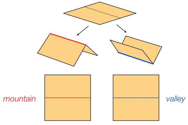
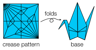
Origami Concepts and Definitions

John C. Bowers, Ileana Streinu,

Crease Patterns

Origami

is concerned with the folding of paper to produce three dimensional realizations in various geometric configurations. Typically, folds are made along straight line segments of the paper which are commonly called creases.

These creases form a planar subdivision of the paper called the crease pattern.

Mathematically, the paper is modeled as the interior region of a (typically convex) polygon. The crease pattern is given by the edges of a planar, piecewise-linear, (typically convex) tiling of the region. The figure to the right shows a crease pattern on a square piece of paper.

In a base, two faces incident on the same crease edge can remain flat, or can be folded. This is formalized by the concept of mountain and valley folds. If the dihedral angle between two faces is larger than pi, then the crease is said to be a mountain fold in the base. If smaller, the crease is a valley fold. If equal, the crease is flat. This is illustrated in the figure below.

Bases

A base

for a crease pattern is a folding of the paper along the crease edges to realize a 3D state. A base can be defined mathematically as a mapping of the vertices of the crease pattern into 3D such that the base is isometric and isomorphic to the flat crease pattern. In other words, the 3D structure preserves the combinatorics of the crease pattern as well as the shape and metric of each of the faces.

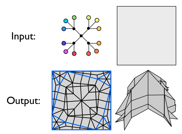
Robert J. Lang further categorized two subsets of bases called projectable and uniaxial in his paper "A Computational Algorithm for Origami Design." These provide for a more strict form of base which Lang showed is amenable to an algorithmic treatment.

A projectable base

is one in which all of the faces are perpendicular to some common plane (typically the xy-plane). The projection of the base onto the orthogonal plane forms a geometric tree, which is called the shadow tree. 
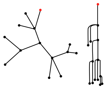
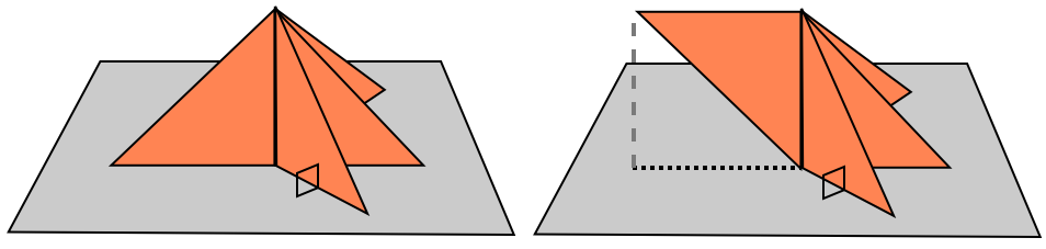
The figure below depicts two different projectable bases with the same shadow tree. In both bases, the gray plane is perpendicular to each of the orange faces of the base. The left figure has an added property, however, that the intersection of the base with the orthogonal plane is equal to its shadow tree.

A uniaxial base

is a projectable base where all the faces of the base lie on the same side of the orthogonal plane, and the boundary of the paper is mapped exactly onto the shadow tree. The figure below shows an example.

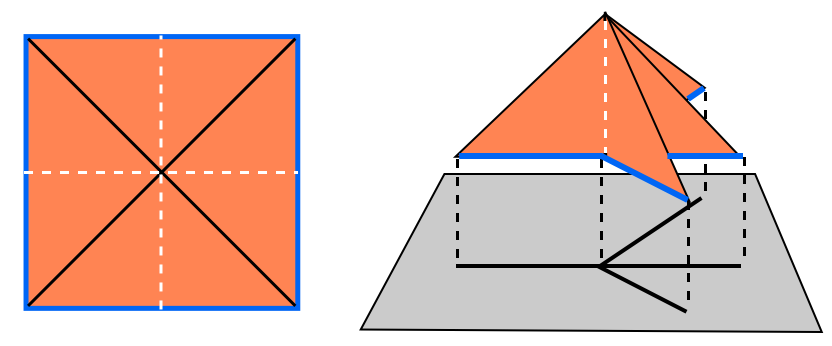
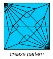
In this figure the crease pattern is shown on the left, and a uniaxial base for the crease pattern is on the right. The orthogonal plane has been shifted downwards so that the shadow tree is clearly visible. The boundary of the paper has been colored blue in both figures, and the diagonal creases are shown in black while the horizontal and vertical creases are depicted with a dotted white line. The reader can clearly see that the boundary of the polygon is folded exactly onto the shadow tree.

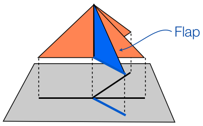
All of the faces that project to the same arc of the shadow tree are called a flap. The uniaxial base in the figure above has four flaps, each of which two faces of the base project to. In a uniaxial base, the internal nodes of the shadow tree correspond to "hinge" creases that are perpendicular to the orthogonal plane. Rotations of shadow tree arcs correspond to rotations of the flaps around the internal nodes correspond to rotations of the flaps about the corresponding 
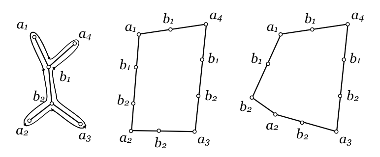
hinge crease. The figure below shows two uniaxial bases for the same crease pattern as above. These bases only differ by rotation around the hinge creases.


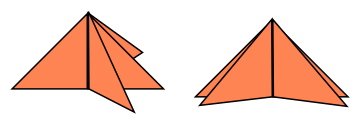
Two uniaxial bases with the same crease pattern.

The term uniaxial is used, because if the shadow tree arcs are aligned, as in the figure below, the boundary of the paper is aligned along a single axis.


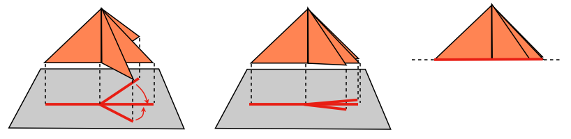
If the shadow tree of a uniaxial base aligns, then the boundary of the paper aligns along a single axis.

Origami Design Problem

The origami design problem

is the problem of generating a crease pattern for a polygonal sheet of paper, such that there exists a base with some desired (think "user-specified") properties. The folding and one cut problem of Demaine et. al is a version of the origami design problem in which a polygonal shape is drawn on the surface of the paper, and a crease pattern is computed so that when folded into a base, a single cut of the paper separates the interior of the polygonal shape from the exterior (for more information on this, please see our list of references on the main page.)

Lang formulated another version of the origami design problem, and solved it with his TreeMaker algorithm: given a desired shadow tree and polygonal sheet of paper, Lang's version of the problem is to produce a crease pattern for the paper such that there exists a uniaxial base whose shadow tree is the input tree.


The origami design problem solved by TreeMaker.

Metric Trees, Doubling Cycles & Lang Polygons

As we saw above, in a uniaxial base flaps can be rotated around hinge creases, which correspond to rotations of the corresponding shadow tree arcs around internal nodes. This allows us to generalize the geometric shadow tree to the concept of a topologically embedded metric tree. Given a shadow tree and a uniaxial base projecting to that shadow tree, a uniaxial base for any other shadow tree which is metrically and topologically equivalent can be reached by simple rotations of the flaps around their hinges. This reduces the problem of generating a crease pattern for a desired geometrically embedded tree to that of generating a crease pattern for a desired topologically embedded metric tree.

Furthermore, we can define a standard alignment of the tree by selecting a root vertex, and "shaking out" the tree so that all other arcs fall downwards. All arcs are thus aligned along the same line, with the topological ordering preserved. This alignment of the tree along a single axes is the reason that the uniaxial bases are called "uniaxial." In the figure below we illustrate the standard alignment (right) of a topologically embedded metric tree (left). Keep in mind that the arcs in the standard alignment have been curved outwards for visualization purposes, but in reality all arcs lie along the same line.


A rooted topologically embedded metric tree (left) and its standard alignment (right).

A doubling cycle

for a topologically embedding metric tree is a polygon generated by walking around (in topological order) the arcs of the tree. Each arc traversed along the walk corresponds to an edge of the same length in the doubling cycle. The leaf nodes are encountered only once, and thus have unique corresponding vertices in the polygon. An interior node of degree d is encountered d times, and is each time marked on the boundary. The figure below shows a tree as well as two different doubling cycles for the tree.


A topologically embedded metric tree and two doubling cycles. The first doubling cycle is a Lang polygon.

If a doubling cycle is a convex polygon such that for each pair of vertices corresponding to leaf nodes, their euclidean distance is greater than or equal to the corresponding distance between the leaves, then we call the doubling cycle a Lang Polygon. In the figure above, the first doubling cycle is a Lang polygon, but the second is not (since by the triangle inequality, the distance between vertices a1 and a2 is less than the distance in the tree between leaves a1 and a2).

In a Lang polygon we call vertices corresponding to leaf nodes corner vertices and those corresponding to interior nodes marker vertices.

Click on the section headings or arrows to open and close them. Java applets may load slowly the first time.

← back